
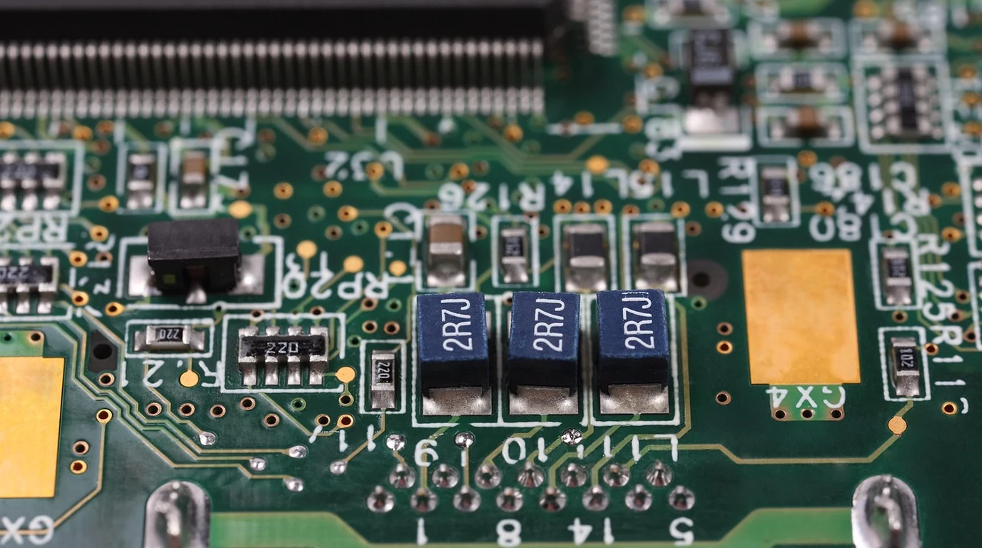
You’ve just poured countless hours into designing a cutting-edge server motherboard, a high-density NVMe storage array, or a next-gen accelerator card. You’re pushing PCIe 5.0, maybe even eyeing PCIe 6.0, and you’re confident your architecture is solid. Then, the first bring-up happens. Intermittent link training failures. Sporadic data corruption. Eye diagrams that look less like an open eye and more like a closed slit. Your heart sinks. You’re staring down the barrel of signal integrity issues, and the clock is ticking on your project schedule and budget.
The silent killer in high-speed digital design isn’t always a catastrophic short or a misrouted trace. Often, it’s the insidious decay of your precious PCIe signal as it travels across what seems like a perfectly reasonable length of copper. At 32 GT/s for PCIe 5.0, and especially at 64 GT/s with PAM4 for PCIe 6.0, those seemingly benign PCB traces become hostile environments. You’re losing signal strength at an alarming rate – we’re talking 36 dB or more across just 10 to 14 inches of standard FR4 or even higher-performance Megtron-6. That’s enough to completely close your eye diagram, turning pristine bits into unrecoverable noise. The choice between a redriver and a retimer isn’t just an engineering detail; it’s the difference between a product that ships on time and one that languishes in debug hell, costing you millions in lost revenue and market opportunity.
For PCIe 5.0 (32 GT/s) and beyond, redrivers are suitable only for very short, well-controlled links with minimal jitter accumulation. For any significant trace length (typically >10 inches on FR4) or when multiple connectors/cables are involved, retimers are almost always the necessary choice. They regenerate a pristine signal, eliminating accumulated jitter, which redrivers cannot do, preventing costly signal integrity failures.
Why Your PCIe 5.0 Signals Are Dying Over Short Distances
Let’s be honest: the jump from PCIe 4.0 (16 GT/s) to PCIe 5.0 (32 GT/s) wasn’t just a doubling of bandwidth; it was a fundamental shift in the signal integrity challenge. And PCIe 6.0 (64 GT/s PAM4) takes that challenge to an entirely new level. The “costly trap” many engineers fall into is underestimating the brutal physics at play. You might think, “It’s just a few more inches of trace, how bad can it be?” The answer, unfortunately, is “catastrophically bad.”
At these blistering speeds, the electrical signal isn’t just traveling; it’s fighting a losing battle against the very medium it’s traversing. Three primary culprits conspire to degrade your signal:
- Skin Effect: This phenomenon causes high-frequency currents to flow predominantly on the surface (or “skin”) of the conductor, rather than uniformly throughout its cross-section. This effectively reduces the conductor’s usable area, increasing its resistance at higher frequencies. More resistance means more attenuation.
- Dielectric Loss (Loss Tangent): The PCB material itself isn’t a perfect insulator. The dielectric material (like FR4) absorbs some of the electromagnetic energy as the signal passes through it, converting it into heat. This loss is frequency-dependent, meaning it gets significantly worse as you crank up the gigatransfers per second. Standard FR4, while cost-effective, becomes a major bottleneck at 32 GT/s and is virtually unusable for longer PCIe 6.0 traces without extreme measures. Even premium materials like Megtron-6, while better, still suffer considerable loss.
- Inter-Symbol Interference (ISI): As the signal travels, different frequency components travel at slightly different speeds, and reflections can occur. This causes the “tail” of one bit to bleed into the “head” of the next, smearing the distinct boundaries between bits. The result is a blurring of the signal, making it harder for the receiver to correctly distinguish between a ‘0’ and a ‘1’. This is the primary reason your eye diagram closes.
When you combine these effects, a PCIe 5.0 signal can easily lose 36 dB of its amplitude over a mere 10-14 inches of FR4. To put that in perspective, 36 dB is a reduction in power by a factor of 4000! Your receiver, designed to interpret millivolt-level signals, is now trying to make sense of microvolt-level noise. It’s like trying to hear a whisper in a rock concert – impossible without serious help.
Understanding the Fundamental Difference: Analog Boost vs. Digital Regeneration
This is where the distinction between redrivers and retimers becomes not just important, but absolutely critical. They both aim to improve signal integrity, but they do so in fundamentally different ways, with vastly different outcomes for your high-speed PCIe link.
What Exactly is a PCIe Redriver Doing?
Think of a redriver as a sophisticated analog amplifier. Its primary job is to boost the attenuated signal’s amplitude and apply some frequency-dependent equalization. The key components here are:
- Continuous-Time Linear Equalization (CTLE): This is an analog filter that applies more gain to the higher frequency components of the signal, attempting to compensate for the frequency-dependent losses (skin effect and dielectric loss) that disproportionately attenuate the high-frequency content. It tries to “open” the eye diagram by boosting the attenuated edges.
- Output Driver: After equalization, the signal is amplified to its original voltage swing, making it stronger for the next segment of the trace.
The crucial point about redrivers is that they operate purely in the analog domain. They don’t “understand” the PCIe protocol. They don’t re-sample the data. They don’t regenerate a new, clean clock. This means that while they boost the signal and try to equalize it, they also amplify everything else that has accumulated along the path: noise, reflections, and most critically, jitter. Jitter is the deviation of a signal’s timing from its ideal position. If your incoming signal has 2 picoseconds of random jitter, a redriver will amplify that signal, but those 2 picoseconds of jitter will still be there, potentially even exacerbated by the redriver’s own internal noise. This is why redrivers are often called “linear equalizers” – they linearly process the signal, good and bad alike.
How a PCIe Retimer Completely Reinvents Your Signal
A retimer, on the other hand, is a mixed-signal marvel. It’s far more complex and intelligent than a redriver because it’s protocol-aware and operates in both the analog and digital domains. Its process is akin to taking a blurry, noisy photograph, digitally enhancing it, and then printing a brand new, pristine copy. Here’s how it works:
- Input Equalization (Analog): Like a redriver, the retimer first applies CTLE and sometimes Decision Feedback Equalization (DFE) to open the incoming eye diagram as much as possible, making the degraded signal decipherable.
- Clock and Data Recovery (CDR): This is the magic. The retimer extracts the clock embedded within the incoming data stream. It then uses this recovered clock to re-sample the incoming data. This re-sampling process effectively “cleanses” the signal of accumulated jitter. Any timing variations that occurred before the retimer are discarded, and a new, perfectly timed bit is generated.
- Data Regeneration (Digital): Once the data is re-sampled and re-timed, the retimer regenerates a brand new, pristine digital bitstream. This new signal has a perfectly clean eye diagram, free from the jitter and ISI that plagued the original signal.
- Output Driver: Finally, this regenerated signal is driven out with full amplitude and optimal rise/fall times, ready to travel the next segment of the link as if it were a fresh signal from the source.
Because a retimer completely re-times and regenerates the signal, it effectively resets the jitter budget for the link. This is its most significant advantage. The trade-offs are increased latency (typically around 10 nanoseconds per retimer, which is generally acceptable for PCIe but must be accounted for in latency-sensitive applications), higher power consumption, and significantly higher cost.
When Does a Redriver Just Amplify Your Problems? The PCIe 5.0/6.0 Reality
The “costly trap” for many is assuming a redriver is a universal, cheaper fix. While a redriver is perfectly adequate for PCIe 3.0 or even some PCIe 4.0 applications with short traces and minimal jitter sources, it quickly becomes a liability at PCIe 5.0 and beyond. Why? Because at 32 GT/s, the jitter budget is incredibly tight. Any accumulated jitter, whether from the host, the PCB traces, connectors, or even the redriver itself, can quickly consume that budget and lead to link failures.
Imagine your PCIe link as a relay race. Each segment of the trace, each connector, each component adds a little bit of “noise” to the baton (your signal). A redriver is like a coach who just tells the runner to run faster, but doesn’t fix their clumsy hand-off. The jitter (clumsiness) just keeps accumulating. A retimer, however, is like a coach who takes the baton, cleans it, and hands it off perfectly to the next runner, resetting any accumulated clumsiness. This is why retimers are essential for maintaining the integrity of the PCIe protocol over longer distances or through complex topologies.
Consider a scenario with multiple connectors, such as a server motherboard connecting to a riser card, which then connects to an add-in card. Each connector introduces reflections and impedance discontinuities, which manifest as jitter. A redriver placed after the first connector might boost the signal, but it will also faithfully amplify the jitter introduced by that connector. By the time the signal reaches the add-in card, the accumulated jitter might be so high that the card’s receiver cannot reliably decode the data, leading to uncorrectable bit errors and link instability.
| Feature/Characteristic | PCIe Redriver (Linear Equalizer) | PCIe Retimer (CDR-based) | Critical Impact for PCIe 5.0/6.0 |
|---|---|---|---|
| Core Functionality | Analog amplification and continuous-time linear equalization (CTLE). Boosts signal amplitude and compensates for frequency-dependent loss. | Mixed-signal device with Clock and Data Recovery (CDR). Completely re-samples, re-times, and regenerates a new, pristine digital signal. | Redrivers are “signal conditioners”; Retimers are “signal regenerators.” This distinction is paramount for high-speed links. |
| Jitter Handling | Passes through and may amplify existing jitter (random, deterministic, periodic). Does not remove or reduce jitter. | Completely removes accumulated jitter by re-timing the data to a clean, recovered clock. Resets the jitter budget for the next link segment. | PCIe 5.0/6.0 links have extremely tight jitter budgets. Jitter accumulation is the primary killer, making retimers often indispensable. |
| Protocol Awareness | None. Purely analog, treats the signal as a waveform regardless of its data content. | Protocol-aware. Participates in link training, equalization negotiation, and power management. Can adapt to link conditions. | Retimers ensure robust link training and optimal equalization settings, crucial for high-speed link stability and performance. |
| Latency | Very low, typically <1 nanosecond. | Higher, typically 5-15 nanoseconds per device due to CDR and digital processing. | While higher, 10ns is generally acceptable for PCIe. Multiple retimers in series can accumulate latency, requiring careful planning. |
| Cost (per lane) | Low, typically $5-$10 per device (for 4-8 lanes). | Significantly higher, typically $25-$40+ per device (for 4-8 lanes). | The higher upfront cost of retimers is often dwarfed by the cost of debugging, redesigns, and lost market opportunity from redriver-based failures. |
| Power Consumption | Lower, typically 100-300 mW per device. | Higher, typically 500-1000 mW per device. | Must be factored into thermal design and power budgets, especially in high-density systems with many retimers. |
Where Do These Signal Saviors Live? Strategic Placement for Peak Performance
The placement of redrivers and retimers isn’t arbitrary; it’s a strategic decision based on your link budget, trace lengths, and the number of discontinuities (connectors, vias) in the signal path. The goal is to ensure the signal integrity remains within acceptable limits at every point, particularly at the receiver’s input.
Server Motherboards: The Backbone of High-Performance Computing
In server motherboards, PCIe 5.0 and 6.0 links are ubiquitous, connecting CPUs to chipsets (PCH), CPUs to expansion slots, and CPUs directly to NVMe drives. Typical placement scenarios include:
- CPU-to-PCH Links: These links can be relatively short, but if the PCH is distant or there are many layers of PCB routing, a retimer might be necessary, especially for PCIe 5.0/6.0. Redrivers might suffice for very short, clean runs.
- CPU-to-PCIe Expansion Slots: This is a prime candidate for retimers. The trace length from the CPU to the slot connector can easily exceed 10-14 inches, especially on large server boards. Add the connector loss and the trace on the add-in card, and you’re well past the point where a redriver is effective. A retimer is typically placed near the CPU or just before the PCIe slot connector to regenerate the signal before it enters the slot.
- On-Board NVMe Drives: For M.2 or U.2 NVMe drives directly on the motherboard, if the trace length from the CPU or PCH is significant, a retimer might be required. For shorter paths, a redriver might be considered, but careful simulation is needed.
PCIe Riser Cards: Extending Reach and Flexibility
Riser cards are common in 1U/2U servers and custom enclosures where space is at a premium or specific form factors are needed. They introduce additional connectors and trace lengths, making signal integrity even more challenging:
- Between Motherboard and Riser: The connection from the motherboard to the riser card is a critical point. A retimer is often placed on the motherboard side, just before the riser connector, or on the riser card itself, immediately after the connector. This ensures a clean signal is passed between the two boards.
- On the Riser Card Itself: If the riser card has significant trace lengths to its own PCIe slots, another retimer might be necessary on the riser card to condition the signal before it reaches the add-in card.
External NVMe Backplanes and Storage Enclosures: The Long Haul
For external storage solutions, such as NVMe over PCIe cables connecting to a backplane, the distances become even greater, and the number of connectors multiplies. This is unequivocally retimer territory:
- Cabled PCIe Connections: Any PCIe cable (e.g., SlimSAS, OCuLink, MCIO) introduces significant loss and reflections. Retimers are essential at both ends of the cable – one near the host controller and another near the device (e.g., on the NVMe backplane). This creates a “retimer-to-retimer” link, ensuring the signal is regenerated before and after the cable.
- NVMe Backplanes: On a backplane that hosts multiple NVMe drives, retimers are typically placed near the input connectors from the host and/or near each NVMe drive slot, depending on the trace lengths and topology. The goal is to ensure that the signal arriving at each NVMe drive is pristine, and the signal leaving it is also strong enough for the return path.
The general rule of thumb for placement is to put the signal conditioner where the signal is most degraded, but before it becomes unrecoverable. For retimers, this often means placing them strategically to break up long channels into shorter, manageable segments, effectively resetting the jitter budget at each point.
Your 3-Step Playbook for Choosing the Right PCIe 5.0/6.0 Signal Conditioner
Navigating the redriver vs. retimer decision for PCIe 5.0 and 6.0 doesn’t have to be a guessing game. Here’s a concrete, actionable framework to guide your hardware selection and ensure your designs are robust and reliable.
Step 1: Characterize Your Link Budget and Loss Profile
Before you even think about silicon, you need to understand the electrical reality of your signal path. This is the most critical step, and it requires detailed simulation and measurement.
- Map Your Physical Channel: Document every single component in your PCIe link: the host controller, PCB traces (length, material, layer stackup), vias, connectors (type, number), cables (length, type), and the end-point device.
- Estimate Channel Loss: Use a combination of simulation tools (e.g., Ansys SIwave, Keysight ADS, Cadence Sigrity) and empirical data (material datasheets, connector S-parameters) to estimate the total insertion loss of your channel at the Nyquist frequency (16 GHz for PCIe 5.0, 32 GHz for PCIe 6.0). Remember that a typical PCIe 5.0 link budget allows for around 36 dB of total insertion loss.
- Identify Loss Hotspots: Pinpoint where the majority of the loss occurs. Is it a particularly long trace? A series of connectors? A challenging cable? This will inform your placement strategy.
- Initial Redriver Feasibility Check: If your total channel loss is significantly below the PCIe specification’s maximum (e.g., <20 dB for PCIe 5.0), and you have minimal jitter sources, a redriver might be feasible. However, proceed with extreme caution. For anything approaching or exceeding 25-30 dB, a redriver is highly unlikely to provide a robust solution for PCIe 5.0/6.0.
Practical Tip: Always over-estimate loss and under-estimate performance. It’s cheaper to add a retimer in design than to debug a failing redriver solution in production.
Step 2: Evaluate Jitter Tolerance and Latency Requirements
Jitter is the silent killer, and latency is the performance metric you can’t ignore. These two factors often push you definitively towards retimers.
- Assess Jitter Accumulation: Consider all potential sources of jitter: the host controller’s output, reflections from impedance mismatches (vias, connectors), crosstalk, and power supply noise. If your channel includes multiple connectors, long cables, or passes through complex routing, jitter accumulation will be significant. Redrivers do not mitigate this; retimers do.
- Check Jitter Budget Compliance: PCIe specifications define strict jitter budgets. Simulate or measure the expected jitter at the receiver’s input. If the total jitter (TJ) or random jitter (RJ) exceeds the allowed limits, a retimer is your only reliable option to reset that budget.
- Analyze Latency Impact: While a single retimer’s 10-15 ns latency is usually acceptable for PCIe, multiple retimers in series (e.g., host -> retimer -> cable -> retimer -> device) can accumulate. For extremely latency-sensitive applications (e.g., high-frequency trading, real-time control systems), this cumulative latency must be carefully modeled and validated against system requirements.
- Consider Protocol Complexity: If your link involves complex link training scenarios, hot-plugging, or dynamic power management, a protocol-aware retimer will offer superior robustness and compliance compared to a “dumb” analog redriver.
Practical Tip: If you’re unsure about jitter, err on the side of caution. Jitter-related failures are notoriously difficult and expensive to debug in the field.
Step 3: Factor in Cost, Power, and Design Complexity
While performance and reliability are paramount, practical considerations like budget and engineering effort play a role in the final decision.
- Total Cost of Ownership (TCO): Don’t just look at the per-chip cost. A $5 redriver that leads to a $500,000 redesign and a 6-month product delay is far more expensive than a $40 retimer that works flawlessly from day one. Factor in potential debugging time, compliance testing failures, and field returns.
- Power Budget and Thermal Management: Retimers consume significantly more power than redrivers. Ensure your power delivery network can supply the necessary current and that your thermal design can dissipate the heat, especially in high-density systems with many retimers.
- Design and Layout Complexity: Redrivers are generally simpler to integrate, requiring fewer external components and less complex PCB routing. Retimers, with their digital logic and CDR, often require more careful power integrity design, clocking considerations, and potentially firmware integration for advanced features. However, modern retimers are highly integrated and often simplify the overall signal integrity challenge by handling complex equalization automatically.
- Vendor Support and Ecosystem: Choose signal conditioning chips from reputable vendors with strong application support, comprehensive datasheets, and readily available IBIS-AMI models for accurate simulation.
Practical Tip: For PCIe 5.0 and 6.0, the default assumption should be a retimer. Only deviate to a redriver if rigorous simulation and testing unequivocally prove it meets all performance and reliability metrics for your specific, short, and well-controlled channel.
The world of PCIe 5.0 and 6.0 is exhilarating, offering unprecedented bandwidth and performance. But with great speed comes great signal integrity responsibility. Understanding the fundamental differences between redrivers and retimers, and applying a disciplined, data-driven approach to your design choices, is no longer optional. It’s the bedrock of successful high-speed product development. Choose wisely, and your designs will not only perform but thrive.
Frequently Asked Questions
What is the maximum trace length for PCIe 5.0 without a retimer?
While there’s no single “maximum” length, for standard FR4 PCB materials, a PCIe 5.0 signal (32 GT/s) typically experiences significant degradation beyond 8-10 inches, making a retimer highly recommended for robust operation. Redrivers might extend this slightly for very clean channels, but usually not enough for complex system designs.
Can I use a redriver for PCIe 6.0 (64 GT/s PAM4)?
It is highly unlikely that a redriver alone will be sufficient for PCIe 6.0. The PAM4 signaling and 64 GT/s data rate introduce even more stringent signal integrity and jitter requirements. Retimers, with their ability to completely regenerate the signal and reset the jitter budget, are almost always mandatory for PCIe 6.0 links of any practical length.
What is the impact of retimer latency on system performance?
Each retimer typically adds 5-15 nanoseconds of latency. While this is generally acceptable for most PCIe applications, in systems with multiple retimers in series or extremely latency-sensitive workloads (e.g., HPC interconnects, real-time AI inference), this cumulative latency must be carefully analyzed and accounted for in the overall system design and performance budget.
How do I choose between different retimer vendors or models?
When selecting a retimer, consider factors like the number of lanes supported, power consumption, package size, available equalization features (CTLE, DFE), protocol compliance (PCIe Gen 5/6), and vendor support. Always request IBIS-AMI models for accurate simulation and validation in your specific channel environment.