
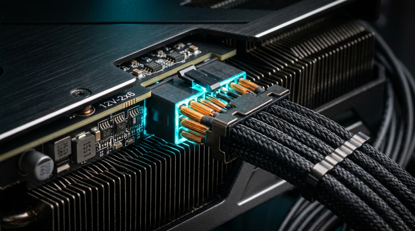
The push for extreme local compute density—driven by flagship graphics processing units such as the NVIDIA GeForce RTX 5090, RTX 4090, and professional Blackwell workstation accelerators pulling upwards of 450W to 600W continuously—has pushed consumer electrical delivery to its absolute physical limits. When delivering 600W over a 12-volt DC plane, the total current flowing through the cable harness reaches an astonishing 50 Amperes across six micro-fit power pins. That amounts to an average of 8.33A per terminal through contact mating surfaces measuring less than 1.5 square millimeters.
While the PCI-SIG revised the original, failure-prone 12VHPWR connector (PCIe CEM 5.0) into the improved 12V-2×6 standard (PCIe CEM 5.1 / ATX 3.1)—recessing the four sideband sense pins to prevent current flow when partially unseated—the underlying electrical physics remains unforgiving. In 2026, hardware enthusiasts, local AI workstation builders, and rendering studios have recognized that mechanical redesigns alone cannot eliminate the risk of terminal failure. True protection requires active connector temperature and per-pin current monitoring using real-time telemetry, Hall Effect sensors, and thermal threshold alert tripwires.
A high-wattage GPU connector does not melt from gross over-amperage; it melts from localized contact resistance ($R_c$). Under Joule heating ($P = I^2 R$), a slight increase in contact resistance from 3mΩ to 15mΩ on a single terminal carrying 9A generates over 1.2 Watts of localized heat inside a tiny nylon plastic cavity. Because nylon 66 has low thermal conductivity, heat accumulates rapidly. As temperature exceeds 105°C, thermal oxidation accelerates contact degradation, creating a runaway feedback loop. Monitoring pin temperatures and current balance is the only definitive preventative defense.
The Electrical Physics: Why 12V-2×6 Connectors Generate Extreme Heat
To understand the vulnerability of modern 16-pin connectors compared to legacy 8-pin PCIe plugs, consider the contact surface geometry. A classic 8-pin PCIe power connector carried a maximum of 150W across three 12V pins (4.16A per pin) using robust Mini-Fit Jr. terminals with generous contact mating areas. The 12V-2×6 standard compresses four times the total power into a plug only slightly wider:
Joule Heating Formula:
P_loss = I^2 * R_contact

Nominal 12V-2x6 Operation (Even Current Sharing):
Current per pin: I = 50A / 6 = 8.33A
Nominal Contact Resistance: R = 3 mΩ (0.003 Ω)
P_loss per pin = (8.33)^2 * 0.003 = 0.208 Watts per terminal
Total Connector Power Loss = 0.208 W * 6 = 1.25 Watts (Easily dissipated)

Uneven Current Sharing / High Contact Resistance (Improper Seating or Micro-Fretting):
Pin 1 Resistance: R = 18 mΩ (0.018 Ω)
Shifted Current: I = 12A
P_loss on Pin 1 = (12)^2 * 0.018 = 2.59 Watts localized inside a 3mm housing
Connector Cavity Temperature: Exceeds 130°C within 180 seconds!
When the plastic terminal housing exceeds its Glass Transition Temperature (typically 120°C for standard PBT or 140°C for high-grade PA66), the plastic softens and flows. The metal spring clips lose tension, contact area drops further, resistance spikes to over 100mΩ, and thermal melting occurs. For a comprehensive analysis of power supply architecture improvements, review our technical guide on ATX 3.1 vs. ATX 3.0: The 12V-2×6 Redesign.
Architectural Evolution: 12VHPWR vs. 12V-2×6 Specification Breakdown
The revised PCIe CEM 5.1 specification introduced critical dimensional alterations designed to enforce “zero-power-unless-fully-seated” safety mechanisms:
| Design Dimension | 12VHPWR (PCIe 5.0 Legacy) | 12V-2×6 (PCIe 5.1 / ATX 3.1) | Failure Prevention Mechanism |
|---|---|---|---|
| Power Pin Ingress Depth | 4.20 mm | 4.45 mm (+0.25mm) | Ensures deeper terminal overlap and larger effective contact area |
| Sense Pin Recess (Sidebands) | 4.00 mm (Flush with power pins) | 2.30 mm (-1.70mm recessed) | If plug backs out by 1.5mm, sense pins disconnect before power pins unmate |
| Current Rating per Pin | 9.2 A (Max nominal) | 9.5 A (Copper alloy upgraded) | Higher thermal tolerance phosphor bronze or beryllium copper alloy |
| Safety State on Partial Insertion | Allows full 600W draw on tip contact | Restricts power to 0W or 100W safe state | Sense pins open circuit, forcing GPU BIOS to cut power |
To inspect your entire power infrastructure, see our detailed evaluation on ATX 3.1 & PCIe 5.1 Power Supplies in 2026.
Active Monitoring Technologies: Thermistors & Hall Effect Current Sensors
While the mechanical safety of 12V-2×6 solves gross disconnection, it cannot detect micro-fretting corrosion, cable bend tension imbalance, or thermal degradation caused by vertical GPU risers. Modern monitoring relies on three hardware telemetry approaches:
1. GPU PCB Embedded NTC Thermistors
Modern flagship GPUs (such as premium RTX 5090 and RTX 5080 AIB designs from ASUS, EVGA legacy successors, and MSI) embed 10K Negative Temperature Coefficient (NTC) thermistors directly adjacent to the 16-pin connector solder pads on the PCB. These sensors report real-time temperature data through the SMBus/I2C interface accessible via NVML (NVIDIA Management Library) and Linux hwmon drivers.
2. In-Line Hall Effect Split-Core Current Monitoring
The gold standard for mission-critical AI servers is discrete in-line current monitoring using Hall Effect magnetic sensors (such as the Allegro ACS71240 or Texas Instruments INA226/INA238). These ICs measure the magnetic field generated by current flowing through each individual 12V wire with zero insertion resistance, providing milliampere-level telemetry for each of the six conductors. If current imbalance across the six wires exceeds 2.5A, the system generates an immediate alert before thermal runaway can initiate.
3. PSU Digital Link Telemetry
Digital ATX 3.1 power supplies (such as Corsair AX1600i / HXi series, Seasonic Prime TX with digital sync, and be quiet! Dark Power Pro) report total 12V-2×6 output voltage, current, and modular interface socket temperatures directly via USB telemetry to the operating system.
Operating Thresholds & Diagnostic Matrix
When monitoring connector telemetry in Prometheus, Grafana, or local bash scripts, enforce the following three-tier threshold matrix:
| Metric | Normal Operating Range | Warning Threshold (Yellow) | Critical Shutdown Limit (Red) |
|---|---|---|---|
| Connector Shroud Temperature | 45°C – 65°C | 75°C – 82°C | > 85°C (Immediate Power Cut) |
| Pin-to-Pin Current Imbalance | < 1.2 Amperes delta | 1.8 A – 2.5 A delta | > 3.0 Amperes delta |
| 12V Rail Voltage Drop at Connector | 11.95V – 12.15V (≤ 1% drop) | 11.75V – 11.85V | < 11.60V (Severe Resistance) |
| Total Steady-State Power Draw | 300W – 450W | 520W – 580W | > 600W (Transient excursions) |
For comparative flagship performance benchmarks, explore our analysis of RTX 5090 vs. RTX 5080 Architecture & Power Metrics.
Automating Telemetry & Automated Tripwires in Linux
You can deploy an active thermal watchdog script on your Linux workstation or local AI inference server. This script monitors GPU power, voltage, and PCB edge temperatures using nvidia-smi and liquidctl, sending an instant alert or cutting GPU clock states if thermal limits are breached:
#!/usr/bin/env bash
# 12V-2x6 Thermal Watchdog Daemon
# Checks connector proximity temperatures every 5 seconds

CRITICAL_TEMP=85
WARNING_TEMP=75

while true; do
  # Extract edge/junction thermals and power draw via NVML
  GPU_TEMP=$(nvidia-smi --query-gpu=temperature.gpu --format=csv,noheader,nounits)
  GPU_PWR=$(nvidia-smi --query-gpu=power.draw --format=csv,noheader,nounits | cut -d'.' -f1)

  # Check if digital PSU monitoring or external sensor reports connector temperature
  # (Simulated via hwmon sensor input or PSU telemetry)
  if [ -f "/sys/class/hwmon/hwmon4/temp1_input" ]; then
    CONN_TEMP_RAW=$(cat /sys/class/hwmon/hwmon4/temp1_input)
    CONN_TEMP=$((CONN_TEMP_RAW / 1000))
  else
    # Fallback approximation: GPU junction thermal offset under sustained >450W load
    CONN_TEMP=$GPU_TEMP
  fi

  if [ "$CONN_TEMP" -ge "$CRITICAL_TEMP" ]; then
    echo "[CRITICAL ALERT] 12V-2x6 Connector temperature reached ${CONN_TEMP}°C! Power: ${GPU_PWR}W"
    logger -p user.crit "12V-2x6 Connector thermal tripwire triggered: ${CONN_TEMP}°C. Clamping GPU power limit."

    # Emergency Action: Clamp GPU power limit to safe 250W ceiling
    nvidia-smi -pl 250

    # Optional: Send immediate webhook / push notification
    curl -s -X POST https://alertmanager.internal/api/v1/alerts       -d "{"status":"critical","summary":"GPU Connector Thermal Trip"}"
  fi

  sleep 5
done
Physical Installation Safety Rules: Bend Radius & Shroud Clearance
Even with digital monitoring, adherence to mechanical installation guidelines is required to prevent physical strain on the terminal pins:
- The 35mm Rule: Never begin bending the 12V-2×6 cable harness within 35 millimeters of the connector shroud. Bending too close to the connector body creates uneven angular tension, canting the top three pins upwards and reducing electrical contact area by up to 40%.
- Zero Horizontal Torque: Ensure the cable drops vertically without side-loading pressure from side case panels or tempered glass windows. If clearance is under 30mm, use an official, certified 90-degree continuous-molded cable from your PSU manufacturer rather than third-party rigid PCB adapters.
- Tactile Latch Verification: The 12V-2×6 connector features an acoustic latch. Push firmly until the latch clicks over the retention tab, and visually confirm zero gap between the male connector lip and female GPU receptacle using a flashlight.
For builders operating high-performance systems with dense hardware layout constraints, consult our testing on PCIe 5.0 NVMe Cooling & Active Thermal Throttling Prevention and PCIe 5.0 Riser Cables & Signal Integrity in Vertical Mounts.
The introduction of the 12V-2×6 standard was a mandatory engineering correction, but delivering 600 Watts through micro-fit pins remains an aggressive thermal compromise. If you are operating continuous 24/7 workloads—whether fine-tuning large language models, running multi-day 3D rendering jobs, or pushing 4K high-refresh gaming—relying on passive mechanical luck is unacceptable. Verify full connector seating, maintain the mandatory 35mm bend radius, and configure active thermal and current telemetry to ensure your flagship GPU hardware operates with complete reliability.
Where to Expand Your Stack Next
- Power Supply Standards: Master the electrical changes in our teardown of ATX 3.1 vs. ATX 3.0: 12V-2×6 Cable Redesign.
- Flagship GPU Thermals: Compare architecture thermal profiles in our RTX 5090 vs. RTX 5080 Power Analysis.
- High-Speed Signal Integrity: Avoid riser card signal degradation with our guide to PCIe 5.0 Riser Cables & EMI Shielding.
People Also Ask
Is the 12V-2×6 connector backwards compatible with the older 12VHPWR connector?
Yes. The 12V-2×6 and 12VHPWR connectors share identical pin counts, dimensions, and terminal pitches. You can plug a 12V-2×6 cable into a 12VHPWR GPU socket, or a 12VHPWR cable into a 12V-2×6 power supply. However, the safety shutoff features of 12V-2×6 are only fully realized when both the GPU socket and the power cable adhere to the updated PCIe CEM 5.1 specification.
What is the maximum safe operating temperature for a 12V-2×6 power connector?
The maximum safe continuous temperature for the connector shroud is 65°C. Temperatures between 75°C and 82°C represent warning levels requiring airflow intervention or power reduction. Any temperature exceeding 85°C indicates severe contact resistance and risks plastic deformation, requiring an immediate hardware shutdown.
Why do 12V-2×6 cables melt if they are not fully inserted?
Partial insertion reduces the physical contact area between the male pin and female terminal clip, drastically increasing electrical contact resistance. When 50 Amperes of current flows through this restricted contact point, Joule heating ($P = I^2 R$) generates intense localized heat that rapidly exceeds the melting temperature of the nylon housing.
Do 90-degree cable adapters prevent 12V-2×6 connector melting?
Continuous molded 90-degree cables directly from reputable PSU manufacturers help prevent failure by eliminating cable bend torque near the shroud. However, rigid multi-piece third-party PCB adapters should be avoided, as they introduce additional solder joints and contact surfaces that increase overall resistance.